PIC serial communication
In this article a pic16f88 is used to send the string "hello, world!" to a computer via serial cable. For this MCU, the Addressable Universal Synchronous Asynchronous Receiver Transmitter (AUSART) mode will be used. As usual, specifics such as register names will more or less only apply to the pic16f88 and xc8, although most MCUs with a UART module will have a similar implementation.
Registers
To enable serial communication, the pins on the MCU must be set, as well as configuring the correct registers.
For the pic16f88, serial communication is done using pins RB5 and RB2.
To configure these pins, the TRISB register must be set.
For example:
TRISB = 0bxx0xx0xx; // output (transmit), set other pins as appropriate
TRISB = 0bxx1xx1xx; // intput (receive), set other pins as appropriate
To enable AUSART, bit SPEN = 1 (part of the RCSTA register) must be set.
Send and receive operations are configured using RCSTA and TXSTA, registers respectively.
These registers are used for both "synchronous" and "asynchronous" modes, so the meaning of some bits depends on which mode.
To begin, we only need to look at the transmit register, TXSTA.
| bit | label | description |
|---|---|---|
| 7 | CSRC |
Clock source select bit: async mode (ignored), sync mode (1 = master mode, clock generated from BRG, 0 = slave, clock from external source |
| 6 | TX9 |
Packet size (1 = 9-bit, 0 = 8-bit) |
| 5 | TXEN |
Transmit enable (1 = enabled, 0 = disabled) |
| 4 | SYNC |
AUSART mode select (1 = sync, 0 = async) |
| 3 | - | not used |
| 2 | BRGH |
High baud rate select (async mode: 1 = high speed, 0 = low speed, sync mode: not used) |
| 1 | TRMT |
Transmit shift register status (1 = TSR empty, 0 = TSR full) |
| 0 | TX9D |
9th bit of transmit data, can be parity bit |
We will be transmitting in asynchronous mode, that is, SYNC = 0.
In this mode, SPBRG sets the baud rate.
#define F_CPU 8000000L
#define BAUD 9600

void
set_baudrate(void)
{
    SPBRG = F_CPU/(16*BAUD) - 1;
}
Thus, to send 8-bit data to a computer in async mode at 9600 baud, TXSTA = 0b00100100.
Now that the MCU is initialised to send data, we look at packaging and transmitting the data itself.
Packaging the data
Data is transmitted serially in bytes (in C, this is of type char or short).
Bytes may be printed in any format: ASCII, decimal, hexadecimal, binary etc.
For this exercise, plain text will be transmitted one ASCII character at a time.
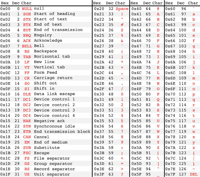
Note that the ASCII table only goes up to 127 (0x7f), higher values (128-255) cannot be represented (see Figure 1).
Normally, sprintf would be used to represent an integer as a string.
However, lacking this library, integers were converted to strings by first splitting them into individual digits, then converting each digit into its corresponding ASCII value.
So, for example, the string "1 25\n" may be represented by the bytes "0x30 0x20 0x32 0x35 0x0A".
Sending a byte
The process the MCU goes through to send data is
- Data is loaded into
TXREGregister - Data is copied automatically to the transmit shift register (
TSR),TXREGregister is cleared and a flag bit,TXIF, is set. (When the interrupt flag enabledTXIE = 0,TXIF = 1calls an interrupt routine.) - Data is transmitted from
TSRregister.TRMTshows the status of theTSRregister:TRMT = 1,TSRis empty,TRMT = 0,TSRis not empty.
For 9-bit transmission (TX9 = 1) the ninth bit should be written to TX9D before writing the 8-bit data to TXREG.
Thus, the code to send data was simply:
STATUS_LED = ON;
while(!PIR1bits.TXIF); // wait until transmit register is empty
TXREG = data;  // load transmit buffer
while(!TXSTAbits.TRMT); // wait until TSR register is empty
STATUS_LED = OFF;
The onboard status LED flashed every time data was sent, which provided some kind of feeback as to whether the program was running.
Sending a string
The first data sent, of course, was "hello, world!".
This was output to a PC and viewd with a terminal emulator.
The development board had a D9 serial port, so a usb-to-serial cable was needed.
This cable had an ftdi chip, so the ftdi_sio serial driver was required under GNU/Linux.
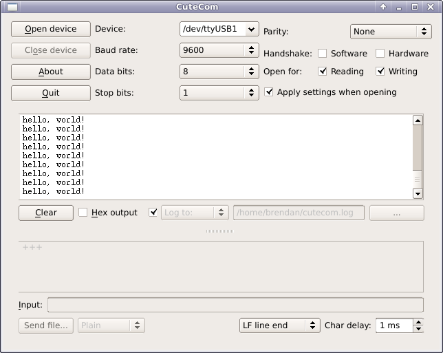
The terminal used was CuteCom. Unusually, there were no problems with this task, and the output from the serial link is shown in Figure 2.
Conclusion
Serial data was transmitted from a pic16f88 dev board to a PC via a serial cable.