LCD hello world
This article details the compilation and write of program to display text on a 4x20 HD44790 LCD using a AT90S2313 microcontroller.
Parts list
For this guide, you will need all the parts used in the avr_blink_program as well as:
- an HD44780 LCD display (e.g. html, with datasheet pdf)
- a 20-50k trimpot
- a 1k resistor
- headers and wire
- tools
The AT90S2313 MCU and Olimex AVR-P20 development board are now well deprecated. But it's what I have, and with portable code, switching to different hardware should be as simple as changing a header file. This board requires 9 - 12VDC, so the -5V and +5V rails of the power supply were used (see power_supply_breakout).
Procedure
First, the original avr_blink_program was recreated with a few updates. First, as udev is no longer used by default in Linux, a guide was followed to install it. After this, I again seemed to have trouble getting the programmer to appear in the devices. For future reference, this fixed the problem:
/etc/udev/rules.d/50-usb.rules

SUBSYSTEM=="usb", ATTR{idVendor}=="16c0", ATTR{idProduct}=="05dc", MODE="0660", GROUP="uucp", SYMLINK+="AVRasp"
Then, the blink program was updated to (hopefully) make it more portable. From the experience in writing portable code (see pic_compiler_comparison), the approach taken was to compare the pic_blink_program and avr_blink_program and try to come up with a common program that could be used for both. This was done by removing differences and putting them in a header file, which can then be changed depending on the hardware. It acts like an "abstraction layer" between the code and the hardware. The main blink program is listed.
/*
 * author: bto
 * date: 20 jun 2020
 * brief: a portable blink program
 */

#include "olimex_avr-p20.h"

int
setup(void)
{
    INIT_LED0;
    LED0_OFF;

    return SUCCESS;
}

int
main(void)
{
    setup();

    while(TRUE) {
        TOGGLE_LED0;
        _delay_ms(1000);
    }

    return SUCCESS;
}
Not only is this simpler to maintain, it is largely self-documenting. This approach will be maintained moving forward.
Key to this program is the "olimex_avr-p20.h" file:
/*
 * author: bto
 * date: 20 jun 2020
 * brief: definitions for the AT90S2313 MCU and Olimex AVR-P20 dev board, and any components
 */

#include "avr/io.h"
#include "util/delay.h"
#include "useful.h"

// MCU
#define __AVR_AT90S2313__ 1
#define F_CPU 10000000UL

// LED 0
#define INIT_LED0 setbit(DDRB,DDB7) // set LED as output
#define LED0_ON  clrbit(PORTB,PB7)
#define LED0_OFF setbit(PORTB,PB7)
#define TOGGLE_LED0 togbit(PORTB,PB7)

// Button 0, low when pressed
#define INIT_BUT0 clrbit(DDRD,DDD2) // set button as input
#define BUT0_PRESS !(readbit(PIND,PIND2)) // read pin, flip
The makefile used is also listed.
CC=avr-gcc
MCU=at90s2313
CFLAGS=-mmcu=$(MCU) -Os

all: clean build

clean:
        rm -f *.hex *.o

blink.o: blink.c
        $(CC) $(CFLAGS) -c blink.c -o blink.o

build: blink.o
        $(CC) $(CFLAGS) -g blink.o -o blink-main.o
        avr-objcopy -O ihex blink-main.o blink.hex

install:
        avrdude -c usbasp -p 2313 -P /dev/AVRasp -U flash:w:blink.hex:i
After that came the process of soldering up the perfboard so the LCD could be attached (see Figure 1a).
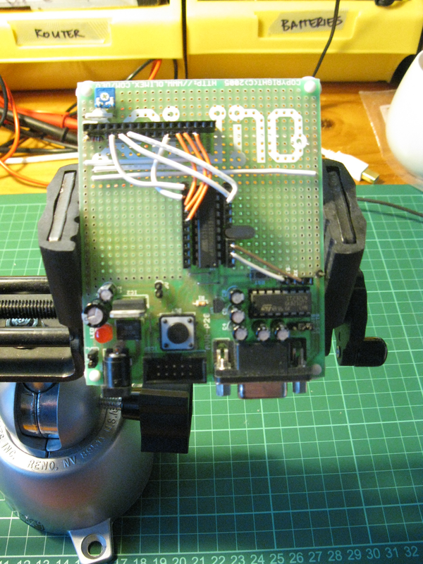
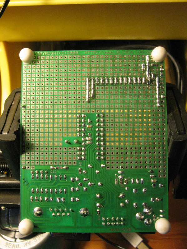
This was my first time working with perfboard, so it took some time to learn how to make solder traces. The method settled upon was to add a blob of solder to a row of pads, then bridge them one-at-a-time (see Figure 1b). Finally, the trimpot was used as the pull-up resistor of a simple voltage divider to control the LCD brightness.
Debugging
After attaching the LCD and powering on, a lot of debugging was still needed to get things working. The use of headers and wiring was essential for this. The following tips were helpful during debugging:
- checking the power
- checking the LCD contrast
- checking the register direction is set to input/output correctly
- check the voltage on the LCD pins is what you think it should be
and, if all else fails:
- read the documentation.
Originally, the LCD data bus was wired to PORTB, which, for this dev board, shares pins with the ICSP. Whenever the MCU was programmed, the LCD showed very strange symbols indeed.
After switching this to PORTD, checking the LCD pins with a DMM helped fix another bug, which was the order of pins.
Originally, the LCD input pins were connected in reverse order to the MCU pins PB3-PB0.
This failed as the program includes commands such as:
lcd_tx(0x01);
Which, if the pins are reversed, effectively sent 10000000 to the LCD instead of 00000001.
Swiching them to be from lowest to highest (i.e. PB0-PB3) fixed this.
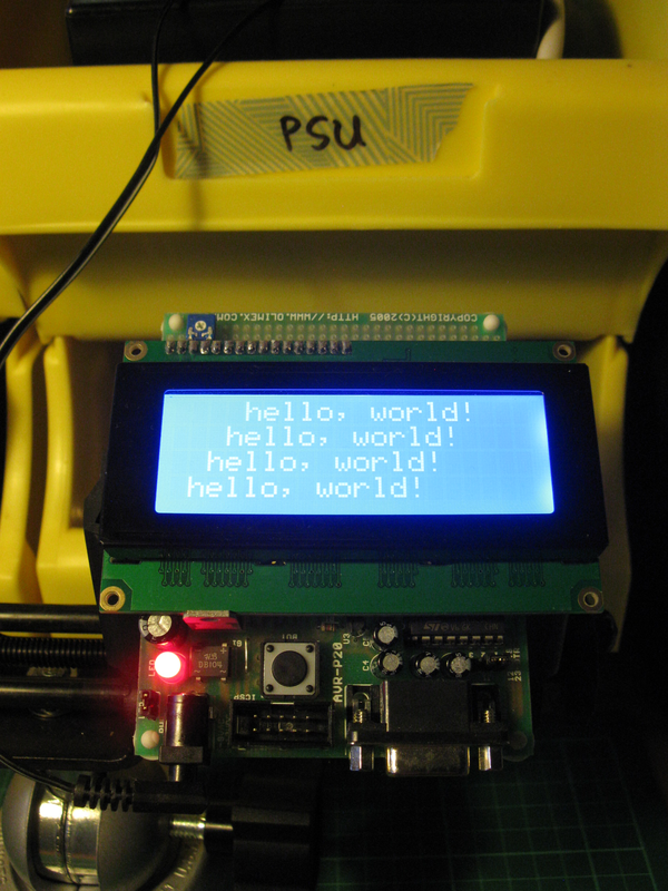
Result
The completed project is shown in Figure 2.
The code can be downloaded (see tar.gz).
Discussion
This LCD is a 4x20 display. However, line 1 wraps to line 3, and line 2 wraps to line 4. Whatever the underlying reason for this is, it led to some real difficulties in printing on the display. Eventually, the following code was implemented to move the cursor to a specific location:
void
lcd_goto(unsigned char r, unsigned char c)
{
    // LCD wraps line 0->2 and 1->3
    lcd_home();

    if (r == 0) shift_cursor_right(c);
    if (r == 1) shift_cursor_right(40 + c);
    if (r == 2) shift_cursor_right(20 + c);
    if (r == 3) shift_cursor_right(60 + c);
}
Conclusion
This was an important step, and ended up taking a few days to implement. From here there are only a few more steps before some really useful projects can be attempted. The next article will be to display text from a PC to the LCD over a serial link.
Update
In terms of memory, this MCU has:
- 2K of flash memory
- 128 bytes of data SRAM (static RAM)
- 128 bytes of EEPROM (electrically-erasable-and-programmable ROM) in a separate data space.
After a lot of investigation, I eventually figured out how to store strings in flash by using the following library:
`#include "avr/pgmspace.h"
This was added to the lcd_driver.o object and compiled to access the relevant functions.
For a bit of fun, I programmed a simple "Magic 8-Ball" program.
/*
 * author: bto
 * date: 19 jun 2020
 * blink program for __AVR_AT90S2313__ on an olimex AVR P20 dev board
 */

#include "olimex_avr-p20.h"
#include "avr/interrupt.h"
#include "avr/pgmspace.h" // store strings in flash, otherwise they will be stored in RAM, of which there is only 128 Bytes
#include "lcd_driver.h"
#include "uart.h"
#include "magic_8_ball.h"

unsigned char rand;
unsigned char i;

ISR(INT0_vect)
{
    _delay_ms(100); // debounce
    TOGGLE_LED0;
    lcd_clear();
    lcd_goto(0,0);
    lcd_print_pgm(PSTR("Shake shake shake"));
    _delay_ms(1000);
    lcd_printc('.');
    _delay_ms(1000);
    lcd_printc('.');
    _delay_ms(1000);
    lcd_printc('.');
    _delay_ms(1000);
    lcd_clear();
    lcd_goto(0,0);
    display_result();
}

void
display_result(void)
{
    if (rand == 0)      lcd_print_pgm(PSTR("It is certain."));
    else if (rand == 1) lcd_print_pgm(PSTR("Definitely."));
    else if (rand == 2) lcd_print_pgm(PSTR("Most likely."));
    else if (rand == 3) lcd_print_pgm(PSTR("Outlook is good."));
    else if (rand == 4) lcd_print_pgm(PSTR("Probably."));
    else if (rand == 5) lcd_print_pgm(PSTR("Uncertain."));
    else if (rand == 6) lcd_print_pgm(PSTR("Ask again later."));
    else if (rand == 7) lcd_print_pgm(PSTR("Unlikely."));
    else if (rand == 8) lcd_print_pgm(PSTR("Outlook not so good."));
    else                lcd_print_pgm(PSTR("Don't count on it."));
}

void
blink(void)
{
    TOGGLE_LED0;
    _delay_ms(1000);
}

int
setup(void)
{
    INIT_LED0;
    LED0_OFF; // led off

    INIT_BUT0;

    // interrupts
    setbit(SREG,SREG_I); // enable global intrrupts
    setbit(GIMSK,INT0);  // enable INT0

    // interrupt on falling edge (button push)
    setbit(MCUCR,ISC01);
    setbit(MCUCR,ISC00);

    // setup uart
    //setup_uart();

    // initialize lcd
    DDRB |= 0x0F; // set output pins for LCD
    LCD_BUS = 0x01;

    DDRD  = 0x70; // 0b01110000 set output pins for LCD RS, RW, E
    LCD_REG = 0x00;

    setup_lcd();
    _delay_ms(100);
    lcd_print_pgm(PSTR("Magic 8-ball"));
    rand = 0;

    return SUCCESS;
}

int
main(void)
{
    setup();
    while(TRUE) {
        for(i=0; i<100; i++) { // calculate rand 100x per second
            rand = (rand + 1) % 10;
            _delay_ms(10);
        }
        shift_display_right(1);
    }
    return SUCCESS;
}