AD595 circuit
The motivation for this article was to learn about the AD595 amplifier and how to correctly wire it up. The AD595 chip takes the voltage output of a thermocouple (usually measured in μV) and amplifies+offsets it such that it can be read by the analogue input pin of a MCU.
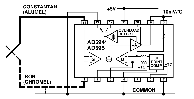
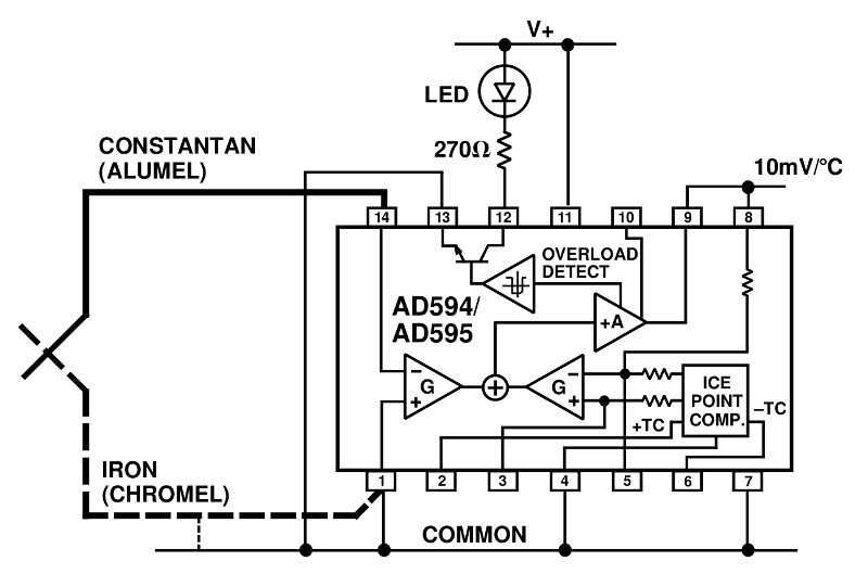
Two circuits were taken from the datasheet (see pdf) for this. The first allowed measurement of positive temperatures only (Figure 1a) and the second was the same circuit with an LED to indicate open circuit on the thermocouple (Figure 1b).
Thermocouples produce a voltage proportional to temperature. They can only measure relative temperatures, so a reference temperature is provided by an onboard thermocouple that uses the temperature sensitivity of silicon. Negative temperatures can be measured by using both positive and negative supply voltages.
This particular model is an AD595A, which has the following specifications:
| Characteristic | Value |
|---|---|
| Transfer function | 10mV/C |
| Error at 25C | +/-3C |
| Max -Vs +Vs range | 36V |
| Alarm voltages | +Vs |
So for -Vs = 0V and +Vs = 5V, the amplifier has a theoretical range of 0 - 500C. The full temperature range for K-type thermocouples is -100C to 1250C.
Testing
To test, the chip was wired up on a breadboard. For the thermocouple, the red (constantan, -ve) lead was connected to pin 14 and the yellow (iron, +ve) lead to pin 1.
I didn't have anything with a known temperature, so I measured mine and got 81.4mV. Using the transfer function of 10mV/C leaves me at a temperature of about 8C which was too low. Ambient temperature was about 5.5mV, which corresponds to about 0.5C, which was also too low. These voltages were stable but something was wrong with either the chip, the wiring or the thermocouple.
After checking the conections, two problems were found. First was a faulty connction to the thermocouple itself. Second was the fact that pin 1 had to be connected to ground (shown in a dashed line in Figure 1).
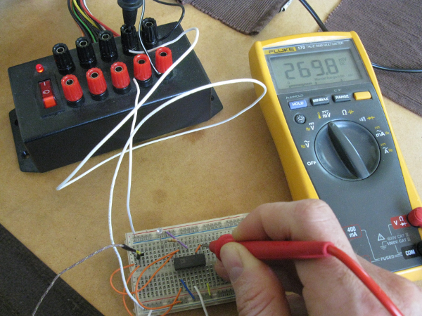
After that my temperature was a more healthy 373.2mV (37.3C) and the ambient temperature was 269.8mV (27.0C) (see Figure 2a).
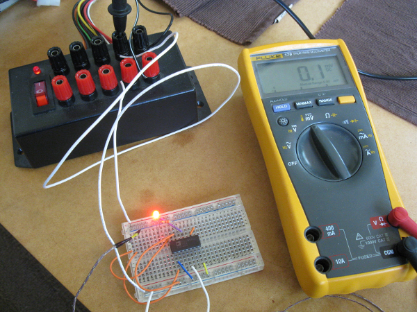
Once the circuit was debugged, an LED and 330kΩ was added to indicate open circuit (see Figure 2b).
Conclusion
The AD595 amplifier worked as described. Temperature was inferred from the voltage reading from the pins. A future article will use an mcu and analogue to digital conversion to log temperature over a serial link.