Power supply breakout
Introduction
A benchtop power supply is a requirement of almost every electronics project. There are many available and they vary in price depending on the number of voltages and rails they provide. However, most people who've built a computer or two will have a spare ATX PSU lying around. The purpose of this project is to breakout the standard 20 pin molex connector into banana plug binding posts to create a benchtop power supply.
Most newer power supplies have 24pin molex connecters. This one had the slightly older 20 pin connector. The pin-out diagram is shown in Figure 1.
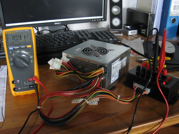
The first step was to power on the PSU by shorting PS_ON (pin 14) to GND.
The next step was to measure the actual voltages from each pin with a DMM.
They were within +/-0.2V of the nominal value, with the exception of the -12V rail, which was closer to -11V.
It became clear during measuring that voltages of the same designation were on common rails. All grounds were also on a common rail. The voltages rose slowly to a steady state, which may explain why some measurements of the +5V rails differ slightly. The PWR_OK pin was simply another +5V rail.
The next step was to design the layout of the circuit board (see Figure 2).
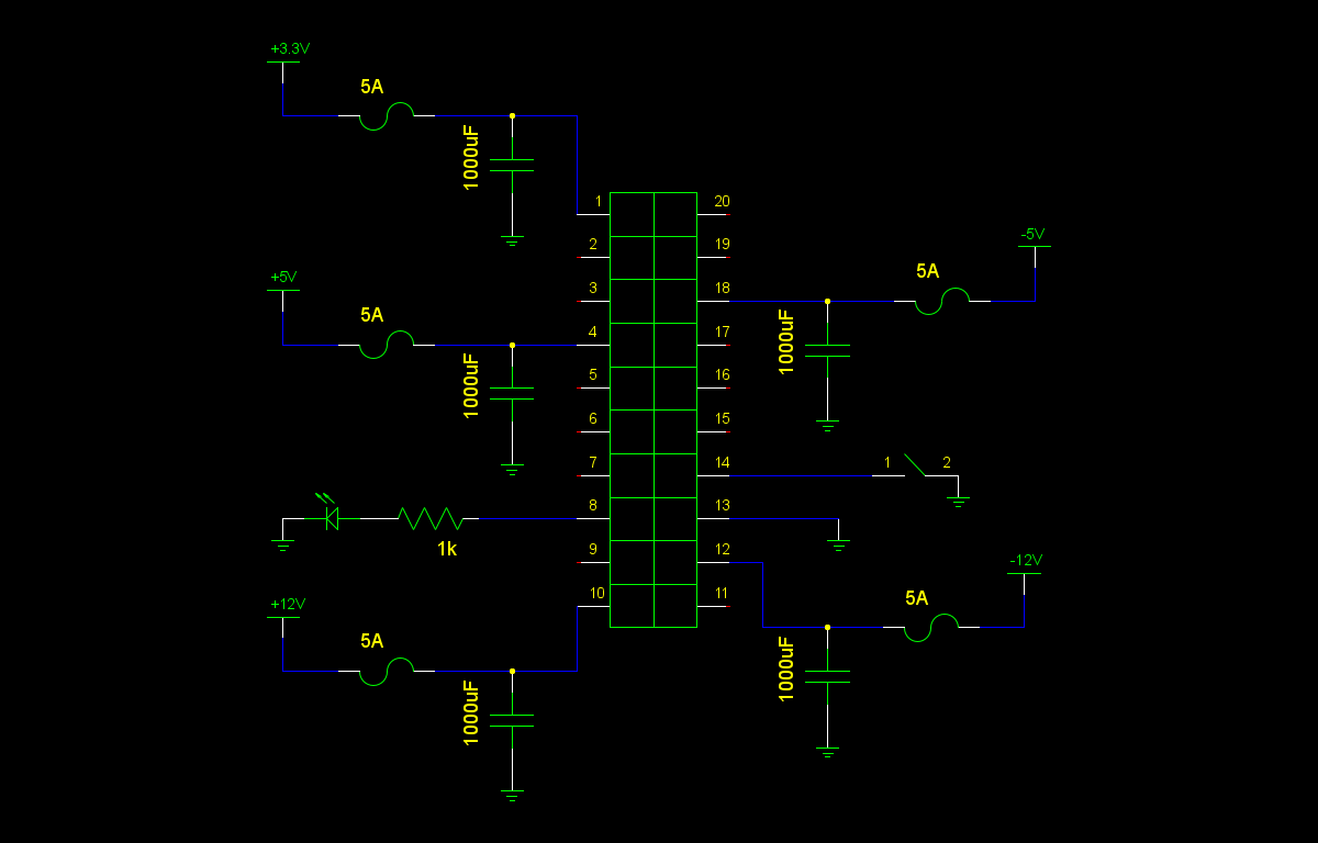
Since ATX PSUs are switch-mode power supplies, capacitors were used to smooth the voltage. In addition, fuses will be used to stop me doing something stupid like hooking up a DC motor that's too big and blowing up the PSU. Note the 20-pin "connector" in this figure has an different pin layout, but they're still correctly wired up.
Parts list
For this project you will need:
- an ATX PSU
- 5 1000uF capacitor
- a 1k resistor
- a rocker switch
- 10 banana plug binding posts
- 5 x fuses (various ratings) and fuse mounts
- stripboard
- a project box
This was a 400W ATX PSU. The current ratings for the +3.3V, +5V, -5V, -12 and +12V rails were 28A, 40A, 0.3A, -0.8A and 17A respectively. Check the maximum current ratings for each of the rails and buy fuses to match. Also, make sure the fuse mounts fit in the stripboard holes.
Procedure
The first step was to drill the holes in the project box for the various components. If you have the time, build the circuit first and then estimate the size of the project box you'll need. It's worth taking your time with the layout and cutting as this will have a large bearing on the quality of the finished project. Getting two project boxes in case you mess up the first one, may be worthwhile. Spare boxes are not a problem.
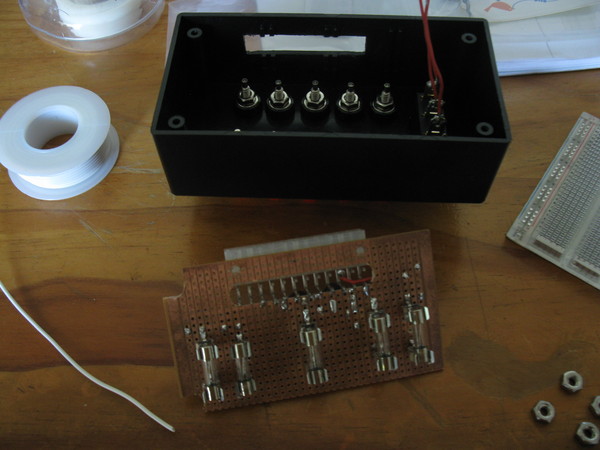
When the components arrived, it quickly became clear that the pins for the molex connector did not fit in the stripboard holes. They were both thicker and spaced differently. To solve this, a horizontal slot was cut in the stripboard, and the pins connected by solder and short lengths of wire to the stripboard rails. A bit of creativity was involved in matching reality to the neat looking circuit diagram. Design it so that the fuses face outwards so that you can change them when they blow (see Figure 3).
As you go, check the colored wires on the molex connector to make sure you connect up the right pins.
While soldering, make sure you put the capacitors in the correct way, that is, negative pin to ground (or to the rail if it is negative voltage.)
For each rail, check for open ciruit between molex and fuse with a multimeter.
For the box, first wire up the LED to a 5V rail and the switch to the PS_ON pin.
Test this by turning on the ATX PSU with the switch.
Wire all the ground banana plug standoffs to a ground rail.
Then wire up the rails to the outputs in your preferred order.
Checking whilst building helps to keep the errors small ones. For instance, one of the connections broke when assembling the box, and two banana plug outputs were swapped, but these kind of faults are eaily fixed. The final voltages were 3.32V, -10.95V, -4.76V, 5.03V and 12.00V.