Rotary encoder
This article implements a rotary encoder to control the brightness of an LED with PWM. It builds on previous articles pwm_led_control and pic_compiler_comparison.
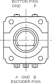
The encoder used here is the PEC11-4215F-S24 (see pdf) which is an incremental encoder with a non-latching button. It turns in discrete steps, where each step produces a square-wave signal (see Figure 1).
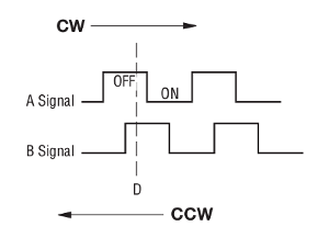
These pulses can then be read by an MCU and used to determine the direction of the turn and the number of steps taken. Looking closely at this figure, if D = AB, then, moving clockwise, D = 11, 01, 00, 10 in turn.
Parts list
You will need all the parts used in the pwm_led_control and:
- a rotary encoder (html)
Procedure
The wiring diagram for this encoder is shown in Figure 2.
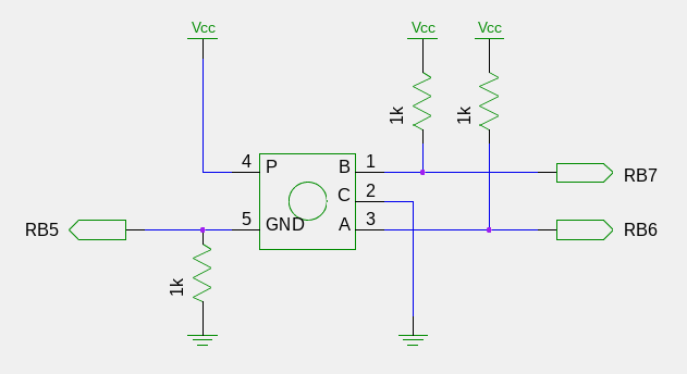
This circuit has one pull-down and two pull-up resistors.
When active, they keep the voltage close to zero or Vcc respectively.
These resistors are often needed for logic circuits to ensure that input pin values are read as 0 and 1.
The resistor values here are not strict - you could probably use anything around 1kΩ.
Interrupts were used to handle input from the rotary encoder.
This is because encoder values change rapidly and I was worried about errors as a result of missing a step.
For the pic18f4550, PORTB pins <RB7:RB4> are best suited for interrupt-on-change.
Encoder pins ENC_A and ENC_B were connected to MCU pins RB6 and RB7 respectively.
Interrupt-on-change for PORTB is for input only. The weak internal pull-ups for PORTB are not enough to pull an input up to logic 1 (although they are for an unconnected pin). So, as mentioned previously, external pull-up resistors were required for the MCU to detect a change.
Encoding
Each encoder position was read by combining the two encoder pin values. Referring again to Figure 1, the sequences of encoder position values are
| sequence | direction |
|---|---|
| 00, 01, 11, 10 | clockwise |
| 10, 11, 01, 00 | counter-clockwise |
(You might recognize these numbers as counting in gray code (see html).)
Taking any two consecutive values in these sequences can be interpreted as a step in that direction. So a clockwise step has a value of either 0001, 0111, 1110 or 1000. Similarly, a counter-clockwise step has a value of either 1011, 1101, 0100 or 0010. There are two additional cases that need to be handled in the code: a combination of two of the same position (e.g. 0000), and any other combination (e.g. 0011). Thus, the encoder routine can be written as
enc_pos = (ENC_A << 1) | ENC_B;

if (enc_pos != prev_enc_pos) {
    enc_dir = (enc_prev_pos << 2) | enc_pos;
    if (enc_dir == 0b0001 || enc_dir == 0b0111 || enc_dir == 0b1110 || enc_dir == 0b1000) {
        // clockwise step
    }
else if (enc_dir == 0b1011 || enc_dir == 0b1101 || enc_dir == 0b0100 || enc_dir == 0b0010) {
        // counter-clockwise step
    }

    enc_prev_pos = enc_pos;
}
Since every possiblity is handled, this turns out to be very robust code.
Now to write code that works. As always, you should start with the simplest program that works. Then, as you add code, make sure the program continues to work. So, following this approach, the code began with (pwm_led_control). Then code that toggled the LED when the encoder button was pressed was added. Finally, the encoder routine (above) was added to change the brightness of the LED.
The entire code and makefile (gz) can be downloaded for your use.
Result
A video of the result is shown in Video 1.
Discussion
While the code is robust, it is possible to get some errors by spinning the dial wildly. This is likely due to the time it takes for the interrupt to handle the incoming signal and could possibly be solved with the use of a buffer. This should be done for a more critical application, which raises the question, why use a rotary encoder for this at all? Why not use a potentiometer?
Rotary encoders output binary values whereas potentiometers output a variable resistance. Both can be used with an MCU, but which one you use really depends on what you're trying to control. Generally, rotary encoders should be used for discrete systems and potentiometers for continuous systems.
A good application for a rotary encoder would be control of a stepper motor, switching between settings, navigating a menu etc. All of these systems change in discrete increments and possibly have no limits (as defined by some physical maximum). Rotary encoders need 2-3 digital IO pins.
Good aplications for a potentiometer would be for volume control, fan speed, screen brightness, tuning a radio etc. Systems where where there are hard limits and fine adjustment is preferable. Potentiometers would need an analogue IO pin, or no pin if you are not interfacing with an MCU.
The most important thing is to consider your application. and put some thought into what functionality you want your component to have. Upon reflection, the use of a rotary encoder for brightening an LED (if it were the end goal) is a terrible choice! Even just for controlling PWM, a pot would be a better choice as it has hard limits (0-100%). Fortunately for me, this is just a learning exercise.
Conclusion
A rotary encoder was implemented using interrupts.