PWM LED control
The motivation for this article was the ability to control devices using pulse-width modulation (PWM). A PWM voltage is a square-wave signal. The mean voltage of this signal is changed by changing the fraction of time the voltage is on (known as the duty cycle) during each period (see Figure 1).
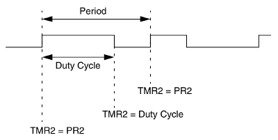
So, for example, the mean voltage for a 50% duty cycle is half the supply voltage.
Parts list
The hardware used was:
- an Olimex PIC-USB-4550 dev board (schematic gif)
- a picstart plus clone (e.g. html with datasheet pdf)
- a USB cable and a 4-pin parallel cable
- a digital multimeter
- a power supply
Background
Some MCUs, like pic18f4550, however, have a built-in PWM module. For this MCU, the Timer2 module controls the PWM period, and the CCP module controls the PWM duty cycle. In this article, a PWM module will be used to control the brightness of an LED.
PWM period
The PWM period is controlled by the Timer2 module.
This timer is in turn controlled by the T2CON register as described below:
| bit | label | description |
|---|---|---|
| 7 | - | unimplemented |
| 6-3 | T2OUTPS3:T2OUTPS0 |
Postscaler (0000 = 1:1, 0001 = 1:2 ... 1111 = 1:16) |
| 2 | TMR2ON |
Timer2 enable (1 = on, 0 = off) |
| 1-0 | T2CKPS1:T2CKPS0 |
Prescaler (00 = 1, 01 = 4, 1x = 16) |
Thus for the maximum prescaler/postscaler combination of 256, T2CON = 0b01111111.
The PWM period is determined by the PR2 value as follows:
PWM Period = 4*(PR2 + 1)*TOSC*(TMR2 Prescale Value)
where TOSC is the external clock period, in this case, 1/20e6 = 5e-8.
The TMR2 value is incremented on each instruction cycle (FOSC/4).
When TMR2 == PR2, the main loop is interrupted and the following routine performed:
TMR2is clearedCCPxpin is set as either on or offCCPRxHis latched toCCPRxL
with the following caveats:
- If the PWM duty cycle value is 0, the
CCPxpin will not be set. - If the PWM duty cycle value is longer than the PWM period, the
CCPxpin will not be cleared.
The CCPx and CCPRx registers are part of the PWM module.
PWM duty cycle
PWM is controlled via CCP (capture/compare/pwm) modules.
The pic18f4550 has two such modules, each operated using a control register, CCPxCON, and a data register, CCPRx.
The control register is:
| bit | label | description |
|---|---|---|
| 7-6 | Unimplemented | |
| 5-4 | DCxB1:DCxB0 |
Bits 0 and 1 of the 10-bit PWM duty cycle |
| 3-0 | CCPxM3:CCPxM0 |
0000 = capture/compare/PWM disabled (resets CCPx module) |
| 0001 = reserved | ||
| 0010 = compare mode: toggle output on match (CCPxIF bit is set) | ||
| 0011 = reserved | ||
| 0100 = capture mode: every falling edge | ||
| 0101 = capture mode: every rising edge | ||
| 0110 = capture mode: every 4th rising edge | ||
| 0111 = capture mode: every 16th rising edge | ||
| 1000 = compare mode: initialize CCPx pin low; on compare match, force CCPx pin high (CCPxIF bit is set) | ||
| 1001 = compare mode: initialize CCPx pin high; on compare match, force CCPx pin low (CCPxIF bit is set) | ||
| 1010 = compare mode: generate software interrupt on compare match (CCPxIF bit is set, CCPx pin reflects I/O state) | ||
| 1011 = compare mode: trigger special event, reset timer, start A/D conversion on CCP2 match (CCPxIF bit is set) | ||
| 11xx = PWM mode |
For PWM output on CCP1, CCP1CON = 0b00xx1100.
The data register is composed of two 8-bit registers: CCPRxL and CCPRxH.
The CCPRxH register is read only.
The CCPRxL register, along with the TMR2 prescale and PR2 register are used to set the PWM duty cycle and period.
PWM Duty Cycle = (CCPRxL:CCPxCON<5:4>)*TOSC*(TMR2 Prescale Value)
Thus, the ratio
 (PWM Duty cycle)/(PWM Period)
 = (CCPRxL:CCPxCON<5:4>)/[4*(PR2 + 1)]
effectively controls the brightness of the LED.
Implementation
For the pic18f4550, CCP1 corresponds only to pin RC2 whereas CCP2 can correspond to either pin RB3 or RC1, depending on whether CCP2MX is 0 or 1 respectively.
To begin with, an LED and resistor were wired up to RC2.
To set up PWM mode, the following was done:
- the
CCPxpin was defined as an output by clearing the appropriateTRISbit. - Timer2 was enabled and the prescale value set by writing to
T2CON. - the
CCPxmodule was configured for PWM operation. - the PWM period was set by writing to the
PR2register. - the PWM duty cycle was set by writing to the
CCPRxL:CCPxCON<5:4>bits.
First, the correct TRIS bit had to be cleared:
TRISCbits.TRISC2 = OUTPUT; // LED
The clock is 20MHz, so the combined prescale/postscale value was set to 256
T2CON = 0b01111111;
CCP1CON = 0b00001100
Note that CCP1CON<5:4> is set to 0 here.
They will be set again when defining the duty cycle.
TMR2 and PR2 are both 8-bit, so have a maximum value of 255.
For the highest resolution, set PR2 to the maximum value.
PR2 = 0xff;
Thus, the PWM period is:
PWM period = 4*256*256*5e-8
           = 0.0131s
The brightness of the LED can be varied from 0 to 100% by varying the duty cycle from 0 to 4*256 = 1024.
This is the full range for a 10-bit number, but, as we saw earlier, it's stored across two locations.
To implement this, the number was split up using #define commands.
#define DC_HI(val) = (char)(val >> 2)
#define DC_LO(val) = (char)(val & 0b11)

int val = 1023;
CCPR1L = DC_HI(val);
CCP1CONbits.DC1B = DC_LO(val);
A quick blink program was constructed to test
#define DC_HI(val) = (char)(val >> 2)
#define DC_LO(val) = (char)(val & 0b11)
int val;

void
main(void)
{
    TRISCbits.TRISC2 = OUTPUT; // PWM is RC2, pin 17
    CCP1 = PORTCbits.RC2; // PWM output pin
    T2CON = 0b01111111;
    CCP1CON = 0b00001100;
    PR2 = 0xff;

    LED = OFF;

    while(1) {
        val = 1023;
        CCPR1L = DC_HI(val);
        CCP1CONbits.DC1B = DC_LO(val);
        delay_ms(1000);

        val = 0;
        CCPR1L = DC_HI(val);
        CCP1CONbits.DC1B = DC_LO(val);
        delay_ms(1000);
    }
}
The next step was to vary the brightness in a linear fashion. To do this, the main function was changed to
while(1) {
    if (val > 1023) val = 0;
    val++;

    CCPR1L = DC_HI(val);
    CCP1CONbits.DC1B = DC_LO(val);
    delay_ms(1);
}
With this, the LED gradually brightened from off to on about once every second. Ideally the duty cycle and period should be verified with an oscilloscope, but I don't have access to one.
Conclusion
For practical purposes, PWM control has been implemented.
Update: Creating a sine wave voltage using PWM
Creating a sine wave using PWM is one way to convert from DC to AC voltage, so it's worth attempting. The first step towards this is to brighten an LED in a cyclic manner. There were two ways to approach this:
- use a preset wave by cycling through a list of duty cycle values or
- use a numerical method
My preference was to use a numerical method in hopes it would be neater. We know that the gradient of a sine wave is a cosine wave, and the gradient of a cosine wave is a negative sine wave. For an amplitude of 1, we can write this in pseudocode as:
y = [0,1]
dydx = [y[1],-y[0]]
This ODE can be updated numerically. A Euler update simply involves multiplying the gradient by the timestep and adding to the state. For a timestep of 0.1, this can be coded as follows:
int duty_cycle = 0;
int duty_cycle_gradient = 511;

while(1) {
    duty_cycle += duty_cycle_gradient/10;
    duty_cycle_gradient -= duty_cycle/10;
}
Simple, right?
Unfortunately, there is both round-off error (due to the use of ints) and error in the update method.
This error results in the value of duty_cycle either going to 0 or +/- infinity after a sufficient number of cycles.
Each period is roughly 6.3 radians, or 63 steps in our method.
Thus, on the 64th step, the values were reset to 0 and 511.
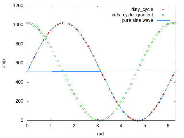
In addition, floats are used instead of ints.
(Compared to using a list of duty_cycle values, using floats is still more memory efficient.)
float duty_cycle = 0;
float duty_cycle_gradient = 511;
int counter = 0;

while(1) {
    counter++;
    if (counter == 64) {
        duty_cycle = 0;
        duty_cycle_gradient = 511;
        counter = 0;
    } else {
        duty_cycle += duty_cycle_gradient/10;
        duty_cycle_gradient -= duty_cycle/10;
    }

    // prevent overshoot
    if (duty_cycle > 511) { duty_cycle = 511; }

    // offset sine wave by 511
    CCPR1L = DC_HI((int)duty_cycle + 511);
    CCP1CONbits.DC1B = DC_LO((int)duty_cycle + 511);
    delay_ms(10);
}
The resulting values and the corresponding sine wave is shown in Figure 2.
In the end, the code was quite concise.
Result
A video of this firmware controlling the brightness of an LED is shown in Video 1.
Future work
Couple this pwm control to a buck-boost circuit for DC to AC power conversion.