AVR serial communication
In this article an at90s2313 is used to send the string "hello, world!" to a PC via serial cable, and echo strings that are sent to it. The first part basically repeats the process of the previous article, pic_serial_communication with a different MCU. The second part, tests the receive operation of the MCU, and is the first step to creating peripheral devices.
Author's note: Unfortunately, the AVR UART library (see html and html) did not seem to work for this chip. If you are using a different MCU, it's ALWAYS better to use the library.
Hardware
The hardware used was:
- an at902313
- an Olimex AVR-P20 dev board
- a serial-to-usb cable
- a power supply (see power_supply_breakout)
On this particular dev board, the RS232 port and MCU socket were not connected by default.
Female header strip was soldered to the board and the RS232 port was wired to the MCU.
Initially the board was wired such that RX was connected to PD0 and TX was connected to PD1.
Registers
To enable serial communication, the pins on the MCU must be set, as well as configuring the correct registers.
The UART module has a data register (UDR) a control register (UCR) and status register (USR). Both the UCR and USR registers need to be set for serial communication. The UCR is described below.
| bit | label | description |
|---|---|---|
| 7 | RXCIE |
rx interrupt enable (see USR.RXC=1) (1 = on, 0 = off) |
| 6 | TXCIE |
tx interrupt enable (see USR.TXC=1) (1 = on, 0 = off) |
| 5 | UDRIE |
data reg interrupt enable (1 = on, 0 = off) |
| 4 | RXEN |
enables rx (1 = on, 0 = off) |
| 3 | TXEN |
enables tx (1 = on, 0 = off) |
| 2 | CHR9 |
chars are 9-bit plus start/stop bit (1 = on, 0 = off) |
| 1 | RXB8 |
9th rx data bit |
| 0 | TXB8 |
9th tx data bit |
The USR is described below.
| bit | label | description |
|---|---|---|
| 7 | RXC |
rx complete flag, calls interrupt (see UCR.RXCIE=1) |
| 6 | TXC |
tx complete flag, calls interrupt (see UCR.TXCIE=1) |
| 5 | UDRE |
UDR empty flag |
| 4 | FE |
framing error |
| 3 | OR |
overrun |
| 2..0 | - | not implemented |
Code
The datasheet for both the at90s2313 (see pdf) and AVR-P20 (see pdf) were referenced heavily during the writing of the UART library.
#define __AVR_AT90S2313__       1

#define F_CPU 10000000L
#define BAUD 9600

#define valbit(reg, bit) ((reg) &   (1 << (bit)))
#define setbit(reg, bit) ((reg) |=  (1 << (bit)))
#define clrbit(reg, bit) ((reg) &= ~(1 << (bit)))

#define STATUS_LED_ON  clrbit(PORTB, PB7)
#define STATUS_LED_OFF setbit(PORTB, PB7)

#define SUCCESS 0
#define FAILURE 1

#include "avr/io.h"
#include "util/delay.h"
#include "avr/interrupt.h"

#include "serial_communication.h"

ISR(UART_RX_vect)
{
    /*
     * UART Rx process
     * 1. char arrives in receive shift register
     * 2. char transferred to UDR (RXC is set)
     * 3. if RXCIE, interrupt called
     * 4. RXC cleared by reading UDR
     *
     * Therefore, this interrupt is called every time a char arrives
     */

     if (valbit(USR,FE)) {} // check framing error before reading UDR
     char c;
     uart_getc(&c); // receive string
     uart_putc(c);  // echo string
     if (valbit(USR,DOR)) {} // check overrun error after reading UDR
}

void
set_baudrate(void)
{
    // set baudrate (p.47)
    UBRR = F_CPU/(16L*BAUD) - 1;
}

void
uart_getc(char *c)
{
    while(!valbit(USR,RXC)); // wait until receive register is empty
    *c = UDR; // get character
}

void
uart_putc(const char c)
{
    // replace newline with carriage return
    if (c == '\n') {
        uart_putc('\r');
    }
    while (!valbit(USR,UDRE)); // wait until data register is empty
    UDR = c; // load data register
}

void
uart_puts(const char *s)
{
    while (*s) { // while there is data in the string
        uart_putc(*s++); // put char in UDR
    }
}

int
setup(void)
{
    DDRB  = 0b10000000; // set PORTB pin 7 as output
    STATUS_LED_OFF;

    // initialize UART
    set_baudrate();

    // status register
    SREG = 0b10000000; // enable global interrupts

    // control register
    UCR  = 0b10011000; // enable rx interrupt, tx, rx (p.46)

    // status register
    USR  = 0b01000000; // clear interrupt flags

    // data registers
    DDRD  = 0b00000001; // set Rx (PD0) as input, Tx (PD1) as output
    PORTD = 0b00000000; // clear values

    return SUCCESS;
}

int
main(void)
{
    setup();
    char tx_data[] = "hello, world!";

    while (1) {
        uart_puts(tx_data);
        _delay_ms(1000);
    }

    return SUCCESS;
}
Debugging
Initially, this code didn't work. To troubleshoot, PD0 and PD1 were set as GPIO pins (i.e. RXEN = 0, TXEN = 0) and switched on and off with a 1000ms delay. They were measured with a DMM to ensure they were working. A different power supply and new MCU were also tried to no avail.
After inspecting the ST232C manual (see pdf) it became clear that the problem was with the wiring. In hindsight it's obvious, but for the benefit of others, always connect the TX pin of one device to the RX pin of the other. The board was rewired such that RX was connected to PD1 and TX was connected to PD0.
Result
This code both transmits data to the PC, and echos data it receives from the PC using interrupts. The ouput is shown below:
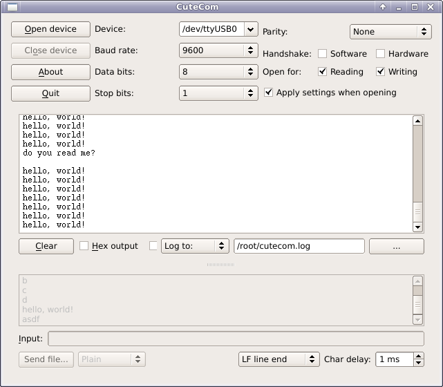
Note the string "do you read me?" was entered in via the terminal and echoed by the MCU.
Conclusion
Serial data was transmitted to and from an at90s2313 dev board via a serial cable.