PIC blink program
This article details the compilation and write of a "blink" program to a PIC18F4550 microcontroller. A "blink" program is the "hello, world" of microcontrollers. Its purpose is to familiarise the user with the hardware and toolchain. After this, you should have the ability to do something useful. The challenge here will be attempt to do this using solely open source tools in GNU/Linux. As it turned out, this wasn't entirely possible with the hardware I had.
Parts list
The following parts were used:
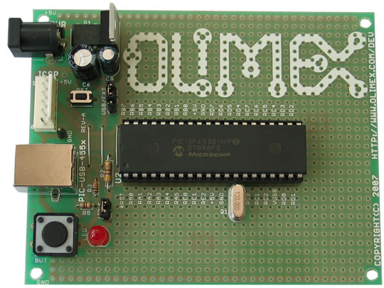
- an Olimex PIC-USB-4550 dev board (see gif)
- an Olimex pic-mcp-usb (a picstart plus clone)
- a USB cable and a 4-pin parallel cable
- a digital multimeter
- a power supply
Choosing a programmer with ICSP header, allows a chip to be programmed without moving it from the development board. You do, however, need a development board with an ICSP header. Also make sure that there is software support for your particular chip/programmer combination.
Upon plugging in your programmer, a device similar to /dev/ttyUSB0 should appear (also check dmesg).
If not, you will need to compile the driver into the kernel.
The programmer and serial-to-USB cable both use an ftdi chip, which is in the kernel menu here:
Device Drivers -> USB Devices -> USB Serial Devices -> FTDI
Compile it as a module, then load.
make modules_install
modprobe ftdi_sio
Check that it's loaded using lsmod. Include in the /etc/conf.d/modules config file to load it during boot.
Toolchain
The software tools used were:
- compiler: sdcc-3.2.0 (see pdf)
- loader: picprog (see html) OR piklab-prog (see html)
- assembler: gpasm
- linker: gplink
- library: gplib
It is always better to use a package manager than installing from source, if you have the option. The last three programs are part of the gputils package (see also pdf). These tools will be used first from the command line, then later using a Makefile.
Procedure
Write or fork your program. A working blink program for the XC8 compiler is listed below:
/*
 * brief: blink program
 * chip:  PIC18F4550
 * clock: 20MHz external
 */

//#include<pic18fregs.h> // specific to SDCC
#include <xc.h> // specific to XC8

#pragma config PLLDIV = 1, CPUDIV = OSC1_PLL2, USBDIV = 1, FOSC = INTOSCIO_EC, IESO = OFF, PWRT = OFF, BOR = ON, FCMEN = OFF, BORV = 3, WDT = OFF, PBADEN = OFF, CP0 = OFF, CP1 = OFF, CP2 = OFF, CP3 = OFF, CPB = OFF, CPD = OFF, WRT0 = OFF, WRT1 = OFF, WRT2 = OFF, WRT3 = OFF, WRTB = OFF, WRTC = OFF, WRTD = OFF, EBTR0 = OFF, EBTR1 = OFF, EBTR2 = OFF, EBTR3 = OFF, EBTRB = OFF

#define INPUT 1
#define OUTPUT 0

// The LED is on pin RD3, the button is on pin RB4
#define LED LATDbits.LATD3 // latch RD3
#define BUT PORTBbits.RB4  // read RB4

void
delay_ms(unsigned long cntr)
{
    while (--cntr != 0);
}

void
blink(unsigned long cntr)
{
    // LED ^= 0x08; // toggle
    // delay_ms(cntr)

    LED = 1; // high
    delay_ms(cntr);
    LED = 0; // low
    delay_ms(cntr);
}

void
button_led(void)
{
    if (BUT != 0)
        LED = 0;
    else
        LED = 1;
}

void
main(void)
{
    TRISDbits.TRISD3 = OUTPUT; // LED
    TRISBbits.TRISB4 = INPUT;  // button

    LED = 0; // LED off

    while(1) {
        //button_led();
        blink(4500);
    }
}
The #pragma config refers to the configuration bits of the chip, not all of them are explicitly set here (see pdf). It might be neater to store these in a separate header file (e.g. config.h) such that they can be included in multiple programs.
Each pin has three registers for its operation:
- TRIS register (data direction)
- PORT register (input/output ports)
- LAT register (output latch)
Check the header file or the documentation to find out exactly what they refer to.
Install your chip in the programmer and plug it in.
Note that both picprog and piklab-prog commands are included here for reference, you only need to use one of them though! First, erase your chip:
picp /dev/ttyUSB0 18f4550 -ep
picprog --device pic18f4550 --pic-serial-port /dev/ttyUSB0 --rdtsc --erase --burn
piklab-prog -p psp -d 18f4550 -t /dev/ttyUSB0 -c erase
and check it's actually erased:
picp /dev/ttyUSB0 18F4550 -bp
piklab-prog -p psp -d 18F4550 -t /dev/ttyUSB0 -c blank_check
Next, compile your C file into hex
sdcc -mpic16 -p18f4550 --use-non-free blink.c
and write
piklab-prog -p psp -d 18F4550 -t /dev/ttyUSB0 -c program blink.hex
picp /dev/ttyUSB0 18f4550 -wp ofile.hex
The first thing you should do after writing a new hex file is to verify it. To do this, read it back from the chip with picp, disassemble it and compare it to the original disassembled hex file. From the command line:
gpdasm -p p18f4550 blink.hex > blink.asm
piklab-prog -p psp -d 18F4550 -t /dev/ttyUSB0 -c read ofile.hex
picp /dev/ttyUSB0 18f4550 -rp ofile.hex
gpdasm -p p18f4550 ofile.hex > ofile.asm
diff ofile.asm blink.asm
Sometimes the software will make this easy for you:
piklab-prog -p psp -d 18F4550 -t /dev/ttyUSB0 -c verify blink.hex
If everything goes well you should get no output. Else, if you didn't erase your chip you may get whatever was leftover from a previous write.
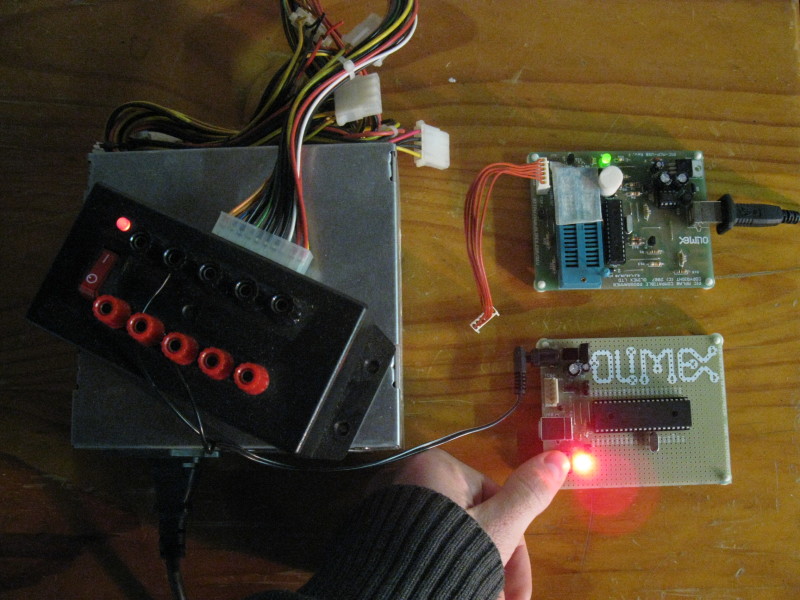
To run the program, unplug the ICSP cable and plug in an external power source. If it works, congratulations! Else you've probably made a mistake somewhere, time to debug.
Debugging
Personally I had a lot of trouble with this hardware. After trying picp, picprog and piklab, I found out that the combination of chip and programmer that I had chosen didn't work with any linux programmer software. Mental note to always check if there was a linux support for hardware before you buy it.
One way to debug is to measure the voltage at the pins with a DMM. I've also written code that flashes the LED after each line and counted the flashes until the program breaks. With more complicated programs, you can use a button to step through lines of your code and measure the pins with a DMM after each line.
You will find all the information you ever wanted (and didn't want) to know from the Microchip data sheet on your paticular chip. Read the device overview and I/O summary.
Further programming
If you manage to get the blink program working, congratulations! Try modifying the code so that the button turns the LED on or off (see Figure 1). Or, if you can do that, randomize the blink delay each time the button is pressed. The possibilities are many. Happy programming.
Optional: Makefile
If you're doing a lot of building, you can use a Makefile to simplify the process. For example:
# hardware
CHIP = 18f4550
FAMILY = pic16
PORT = /dev/ttyUSB0
DEV = psp

# C compiler, assembler, programmer
CC = sdcc
PR = piklab-prog
DA = gpdasm

CFLAGS = -m$(FAMILY) -p$(CHIP) --use-non-free --Werror --opt-code-size
PFLAGS = --target-self-powered true --extra-debug -p $(DEV) -d $(CHIP) -t $(PORT)

.PHONY : all read write verify erase clean

all : blink.hex connect write verify

read :
    $(PR) $(PFLAGS) -c read ofile.hex > read.log

connect :
    $(PR) $(PFLAGS) -c connect > conn.log

write :
    $(PR) $(PFLAGS) -range eeprom -c program blink.hex > write.log

verify:
    $(PR) $(PFLAGS) -c verify blink.hex

erase :
    $(PR) $(PFLAGS) -c erase
    $(PR) $(PFLAGS) -c blank_check

clean :
    rm -f *.o *.cod *.hex *.lst *.err *.asm *.log

blink.hex : blink.c
    $(CC) $(CFLAGS) blink.c
Note: if you copy and paste this Makefile, ensure that the whitespaces are tabs NOT spaces or Make will complain.