Radio communication part 2
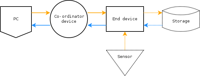
Radio should be used when transmitting data over long distances, or when cables are impractical or undesirable. This is the second in a series of articles that use XBee S2 radios to build a wireless sensor network. In this article, API packets will be sent and received between a PC, co-ordinator device and an end device (see Figure 1).
Parts list
For this article the following parts were used:
Extending the API library
The firmware developed in part 1 (see radio_communication_part_1) was extended to include remote AT commands. In particular, the following packet types were added:
- Remote AT Command Request (
ATRemoteTx) - Remote Command Response (
ATRemoteResponse)
The ATRemoteTx packet is used query or set parameters on a remote radio.
The ATRemoteResponse packet is received from the remote radio and signals whether or not the AT command was successful.
The response packet is sent to the local radio's UART (and, in this case, to the PC).
Hardware
The second Xbee S2 was then flashed with firmware ZIGBEE ROUTER API v.23a7 (as described in the first article).
The first radio still had the ZIGBEE COORDINATOR API firmware v.218C installed.
Since the second radio was remote, it needed it's own power source. This was provided by the 5V and GND pins of a spare development board, which was in turn powered by a 9V battery.
Result
The packet was sent with the local radio and responded to by the remote radio. The destination address was left to the default (broadcast) which meant that every radio that received the message would respond. After fixing a problem with memory allocation and pointers, the software output the following:
Transmit:
  Type: ATRemoteTx
  Frame ID: 0x52
  AT command: BD
  AT value:
  Destination address: 000000000000ffff
  Network address: fffe

Response:
  Frame type: ATRemoteResponse
  Frame ID: 0x52
  Status: OK
  AT command: BD
  AT value: 9600
Discussion
It would be nice if this all went as smoothly as it seemed to, but it did not.
An important debugging technique that was used during this article was being able to make the system fail predictably. This is especially important when you can't see what is going on. For example, turning off a remote radio and sending a ATRemoteTx packet should result in no response packet. With the program written as it is, it just waits indefinitely for a response. While this test may seem trivial, it is extremely important to make sure that the system is actually doing what it appears to be doing.
At the moment it is unclear why there is both a 64-bit destination address and a 16-bit network address is required for packets. The datasheet seems to indicate that the network address is only used once the radio has been added to the network, presumably by the co-ordinator device. See the update below for further investigation into this.
The API packet library has been challenging so far, but the real test will be in the next article.
For that, the software will need to be compiled for both a PC and an ATmega MCU.
The ability to switch between g++ and avr-g++ has been tested along the way, but there will no doubt be other problems.
Conclusion
Second step complete! Communication has successfully occurred between a PC and a remote XBee S2 over radio. The next step is to send and receive data from a remote radio. This is decidedly more complex, as the data will have to be managed by an MCU and stored at the end device.
Update: networks and addressing
The Personal Area Network (PAN) is a special ZigBee networking protocol.
| AT | label | range | description |
|---|---|---|---|
ID |
PAN ID | 0 - 0xfffffffffffffffff | Personal Area Network ID the device should join. If ID=0, the device will join any PAN. |
SC |
Scan channels | 0 - 0xffff | A "bitfield" list of channels to scan when joining a PAN. It is not clear yet what this means, though 0xffff should mean all. |
SD |
Scan duration | 0 - 0x07 | Scan duration when attempting to join a channel. Scan duration = SC*(2^SD)*15.36ms. Maximum duration per channel then is about 2s. |
ZS |
ZigBee stack Profile | 0 - 2 | 0 = network specific, 1 = ZigBee-2006, 2 = ZigBee-PRO |
NJ |
Node join time | 0 - 0xff | The time that the device will allow other devices to join it. If 0xff, device will always allow joining. Time = NJ*1sec |
NW |
Network watchdog t/out | 0 - ? | If non-zero, Router will leave network if it does not receive a valid communication within (3*NW) minutes. Reset after each received packet. |
JV |
Channel verification | 0/1 | Router will verify co-ordinator exists on the same channel after joining and leave if it cannot be found (i.e. if NJ=0xff). |
JN |
Join notification | 0/1 | Router will transmit a broadcast node ID frame on power up and join. This blinks the Assoc LED rapidly on all devices that receive the data. Should be disabled (0) for large networks. |
OP |
Operating PAN | - | Read the operating PAN ID. |
OI |
Operating 16-bit PAN ID | - | Read the 16-bit operating PAN ID. |
CH |
Operating channel | - | Read the operating channel number. |
NC |
Number of children | - | Read the number of remaining end device children that can join this device. |
The following AT commands were then queried of the remote radio:
| AT | Response |
|---|---|
OP |
RSS LED flash, No response packet, |
OI |
RSS LED flash, ATRemoteResponse packet, Status = OK, AT value = 0xc916, and |
CH |
RSS LED flash, ATRemoteResponse packet, Status = OK, AT value = 0x13 |
The values that were returned did indeed match those on the radio.
Pondering these results, it occured that maybe the OP and network address variables only works once a radio is connected to a PAN?
If the co-ordinator PAN ID is set to zero, then a random PAN ID is chosen.
So instead, the co-ordinator and router radios were both then flashed with the following values:
ID = 0x01, that is, the same PAN IDSC = 0xffff, scan all possible channelsSD = 0x0003, for a scan duration of about 120ms per channelNJ = 0xff, always allow nodes to joinNW = 0, no watchdog timeoutJV = 0, don't verify channelJN = 1, notify on joining channel
The previous AT commands were then queried of the remote radio again:
| AT | Response |
|---|---|
OP |
RSS LED flash, ATRemoteResponse packet, Status = OK, AT value = 0x01 |
OI |
RSS LED flash, ATRemoteResponse packet, Status = OK, AT value = 0x12ca |
CH |
RSS LED flash, ATRemoteResponse packet, Status = OK, AT value = 0x16 |
As expected, turning off the remote radio caused these commands to fail.
The next thing that was investigated was the Destination Address variable.
Using the X-CTU software the remote radio was given a Destination Address of 0x01.
The network address was left as 0xfffe.
The co-ordinator radio had a Destination Address of 0x00.
Then, using these two radios, a remote AT command with a Destination Address was used to query the baud rate:
Transmit:
  Type: ATRemoteTx
  Frame ID: 0x52
  AT command: BD
  AT value:
  Destination address: 0000000000000001
  Network address: fffe

Response:
  Frame type: ATRemoteResponse
  Frame ID: 0x52
  Status: Tx Failure
  Dest addr: 0000000000000001
  Netw addr: fffe
  AT command: BD
Failure! The only feedback from the remote radio was the red RSS LED flashed once for 4 seconds upon sending the packet. This indicates that it may yet have received the packet, but did not respond.
Next, using two radios, a remote AT command was sent with a broadcast address that queried the DH and DL variables (destination high and destination low respectively).
Transmit:
  Type: ATRemoteTx
  Frame ID: 0x52
  AT command: DH
  AT value:
  Destination address: 000000000000ffff
  Network address: fffe

Response:
  Frame type: ATRemoteResponse
  Frame ID: 0x52
  Status: OK
  Dest addr: 0013a20040c049c1
  Netw addr: 0b69
  AT command: DH
  AT value: 00000000

Transmit:
  Type: ATRemoteTx
  Frame ID: 0x52
  AT command: DL
  AT value:
  Destination address: 000000000000ffff
  Network address: fffe

Response:
  Frame type: ATRemoteResponse
  Frame ID: 0x52
  Status: OK
  Dest addr: 0013a20040c049c1
  Netw addr: 0b69
  AT command: DL
  AT value: 00000001
This response was very interesting.
Even while the AT command response shows a destination address of 0x0000000000000001, the address of the remote radio returning the response is 0x0013a20040c049c1.
The only explanation I can think of is that these values have different functions, at least for routers.
It is unknown as yet how to set this destination address explicitly.
A remote baud rate query was sent with this new destination address:
Transmit:
  Type: ATRemoteTx
  Frame ID: 0x52
  AT command: BD
  AT value:
  Destination address: 0013a20040c049c1
  Network address: fffe

Response:
  Frame type: ATRemoteResponse
  Frame ID: 0x52
  Status: OK
  Dest addr: 0013a20040c049c1
  Netw addr: 0b69
  AT command: BD
  AT value: 9600
Success! As expected, turning off the remote radio caused this command to fail.