Writing to a microSD card
Most MCUs have very little onboard EEPROM (typically a few kBs). For a standalone device that requires more than this, such as for recording large amounts of data, external storage is required. A convenient solution for this is the use of microSD cards.
In this article, data was written by an ATmega328P to a microSD card. To do this, Roland Riegel's SD-reader library was used (see html). In fact, this library (and the lack of a similar library for PIC MCUs) was one of the main reasons AVR MCUs were originally pursued.
MCU selection
The MCU requirements were, at a miminum:
- 16K flash to accomodate the SD-reader library (6.5KB) and other code and
- preferably a USART module.
The ATtiny167 and ATmega168P/328P MCUs were considered. While the ATtiny167 MCU seemed better suited to collecting data, they were not suited to writing to SD cards. Ultimately, the ATmega328P was chosen because it was supported by the SD-reader library and cost less than the ATmega168P for the associated increase in flash, EEPROM and SRAM. While it may be possible to modify the SD-reader library to support the ATtiny167, the effort did not justify the cost saving (about USD4).
Parts list
For this project, the following parts were used:
- an ATmega328P MCU
- a development board: Boarduino (see html)
- a programmer: USBasp clone, sold by Mengjin Su as a kit (see html)
- a microSD breakout board (see html)
- a full-size breadboard
- a power supply (see power_supply_breakout)
- 8GB microSD card
- USB microSD card reader
- FTDI USB-to-Serial cable
ATmega328p pin mapping
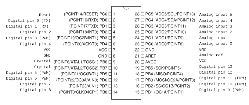
Note that the pins on the boarduino do not match up direclty to those on the MCU. Instead, use the silkscreened numbers to identify the register each pin corresponds to.
SPI communication
The SD-reader library uses SPI to communicate with the microSD card. This involves four pins:
| bit | pin | label | description |
|---|---|---|---|
| PB5 | 13 | SCK |
SPI bus master clock input |
| PB4 | 12 | MISO |
SPI bus master output/slave input |
| PB3 | 11 | MOSI |
SPI bus master output/slave input |
| PB2 | 10 | SS |
SPI bus master slave input |
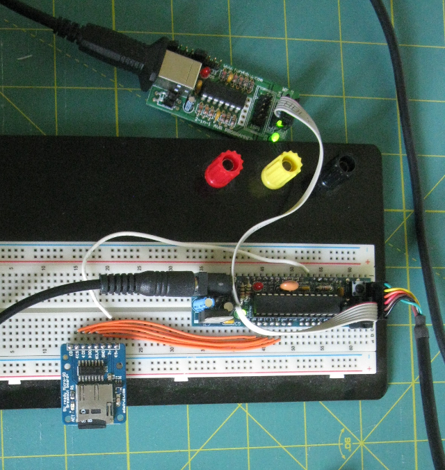
These pins were connected to CLK, DO, DI, CS pins on the microSD card breakout board respectively.
The 5V and GND pins were also wired up (see Figure 2).
SPI is a type of serial communication.
It provides high-speed synchronous data transfer between multiple devices.
A clock signal (SCK) synchronises the data tx/rx and the SS pin is used to select the direction of the data.
The data itself is transferred using the MISO and MOSI bits.
Init, send and receive functions for SPI communication can be found in the ATmega328p datasheet.
These are implemented in the sd_raw.* files in Roland's library.
Unfortunately, the SPI init functions are not separated out from the SD card initialisation.
The code will need some work to be able to transmit data between multiple devices on the same bus.
Program description
The SD-reader library main routine produces a kind of shell that allows basic FAT file commands to be entered. It did not work using CuteCom on GNU/Linux, so a new main routine was written. The remainder of the library was not changed.
The new main routine was composed of C-style functions. These performed basic functions such as changing directories, listing a directory, creating a file, appending to a file, and printing a file. Each of these functions were tested and the output displayed on a terminal via the FTDI USB-to-Serial cable. Ultimately the program should write useful data, such as that from a sensor, to file.
Debugging
Some of the problems encountered while writing the new main routine are listed below:
- MMC/SD initialization failed
- Could not list directory
- Could not locate file
- Could not print file
- Could not append to file
Each of these were solved in turn. The first was simply that the SD card needed to be inserted after powering on the MCU. The second was more difficult, as the SD card was identified correctly. After a lot of effort it was found that the SD card needed to be reformatted with fat32. A 4GB partition was used, but this may not be required. The third was due to not seeking to the beginning of the directory after every listing. The fourth was due to not correctly opening and closing the file for each loop (possibly also related to 1). The fifth was due to correctly seeking within a file and passing the correct string length.
Traditionally in C, a function returns "1" on error. Roland does the opposite with the functions in this library, that is, they return "0" on error. This also led to some fun problems. The library was not modified such that future revisions could also be used.
Results
The after initialising the SD card and opening the partition and filesystem, the main routine loops over the following operations:
- list root directory
- print file position and data length of string to write to UART
- write "blah blah\n" to file "test.log"
The output using a custom Python serial terminal is shown below:
# Settings:
#   port:     '/dev/ttyUSB0'
#   baud:     9600
#   parity:   'N'
#   stopbits: 1
#   bytesize: 8
# Connection open: True
# -------------------------------
                                     0
test.log                             55
file position = 55, data_len = 10
                                     0
test.log                             65
file position = 65, data_len = 10
                                     0
test.log                             75
file position = 75, data_len = 10
                                     0
test.log                             85
file position = 85, data_len = 10
                                     0
test.log                             95
file position = 95, data_len = 10
                                     0
test.log                             105
file position = 105, data_len = 10
                                     0
test.log                             115
file position = 115, data_len = 10
^C
# Done.
As can be seen, the file "test.log" increases by 10 bytes after each write. The file was also checked on a PC using the microSD card reader.
Discussion
The data is in no way useful at the moment, but the ability to write data has been tested. At this point, useful data such as that measured in the article temperature_logging can be stored local to the sensor.
To be even more useful, this sort of data should be time-stamped. For this, a real-time clock is needed. A real-time clock in turn requires a separate crystal, battery, library and interrupt routine. This will be the subject of a future article.
Conclusion
Data was written by an ATmega328p to a microSD card using Roland Riegel's SD-reader library.
Update: Changing the library and increasing the bandwidth
The block size on a fat32 formatted SD card is typically 512 bytes. SD cards are not byte addressable, so for every partial sector access operation (one byte up to the sector size of 512 bytes), the entire sector needs to be accessed. For example, reading a sector byte-by-byte, the sector will be read 512 times. The minimum busy time achievable is by reading or writing 512 bytes at a time (the size of a sector), so that the sector is only accessed once. Therefore a data buffer of 512 bytes should be used.
While Roland Riegel's library worked, and has been a very useful learning tool, there are two more SD card libraries for AVR MCUs that are well maintained
The smaller of the two, Petit FatFS, will be pursued first.